*insert header image of lights*
Hewwo there, glad you’re reading along with my adventure to install Headlights and Turn Lights on a Ninebot Max G30 E-Scooter. This is also the first time am posting any of my works online in a blog format and the first time of me making my own PCB.
My ninebot is my daily commute vehicle and I use it to reach the last mile to supermarkets, Ikke A, friends & for fun tours. However since I tend to have a sleep rhythm that rewards me for being awake in the evening and during nighttime and I have a deep forest near me, this often involves being on dark roads and not being able to see signs and crossing fairies in advance. It is also hard to communicate intent in the complete dark, which is why I thought headlights and turnlights would be super handy.
Btw. if you are using SHFW, you can also set your rear light to light up brighter when braking (always on + car mode).
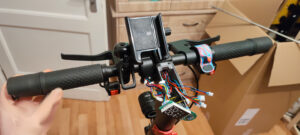
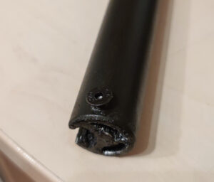
Before / After (headlights vs near distance lights)
*image 1* / *image 2*
While this isn’t intended as as step by step tutorial, following the thoughts that lead to the creation of this, might enyable you to do your own Lighting mods to your Model of E-Scooter.
There are plenty of parts from Scooter, E-Bike and Motorcycle repair shops that can be used as a headlight or turnlights, since many run at 12V and are meant to be screwed onto or into metal frames.
The parts I used are just an idea of what’s possible, you might quickly find something you like.
Also be aware, that there might be local legal restrictions to what you can or can’t do to your vehicle.
Tools you may find useful when implementing this yourself:
- Soldering equipment including flux and something to hold the PCB in place while frying it
- Security Torx bits and a set of allen wrenches for disassembling the handlebar & removing the base cover
- Heatgun or other non-burning source of heat for heatshrinking and reflowing the PCB
- Mobile workbench for propping the scooter up and having it at a back-friendly height
- A vice for holding the handlebar in place while drilling holes and cutting threads
- Fix-All-Flexi or other silicone sealant for waterproofing any cable inlets and the base plate when reassembling
- Cable strippers or steady hands and a knife/scissors (pls don’t cut urself eheheh)
- Tap drills in various sizes + The actual drill + bits (Table drill recommended or ask someone with steady hands to do it with patience), Cutting oil
- Self-Sealing heatshrink (the waterproof one with glue inside)
- Double-Sided tape, WD40, Isoprop and Loctite for sticking, unsticking, cleaning and getting screwed
- Software tools like KiCAD to design your own PCB and send them to a PCB manufacturer
- Small files for deburring if you decide to make holes for cables in metal
A selection of components for your circuits and the actual lights:
- An old USB cable, at least 2 meters long or longer or any other 4+ wires flexible cable, make sure the strands are thick enough to handle the current, a site i found handy was wiresizecalculator.net
- DC / DC Converter with an input range between 32 and 48V if you are using the Ninebot G30 10s stock battery (it is 42v fully charged and voltage might spike higher when electrically braking)
I used Mornsun URB4812YMD-30WR3 (DigiKey Link), it’s also available as a 45W variant if you wannya add other peripherals
For 20s (84V) check out UWTH1D_LD-(20/30)W(F/H)R3 or URF1D_LD-40WR3 or UWTH1D_QB-100W(H/F)R3 - Solid state relais made for at least 120% of the input voltage (operating on the border of the specs may cause it to overheat over time), you don’t wanna use a mechanical relais in a device prone to vibration, this causes wear on the contacts, I used Carlo Gavazzi RP1D060D4 (Reichelt Link) for 10s.
For 20s check out Crydom CN100D05 - RC Connectors like JST BEC 2 PIN and JST SM 4 PIN for the wiring in the base
- A kit of JST 2.0mm PH 2, 3 and 4 PIN connectors for the restricted space in the dashboard, maybe even JST MX 1,25mm 3 PIN + their PCB mounted equivalents
- HIGO Julet 4 PIN Connector (Ali Link) for inside the steering rod, they are water resistant and stay together.
Save yourself a world of pain and get pre-crimped connector sets, you’re not saving much if you don’t already have good crimping tools, you can find these connectors at electronics retailers or on online marketplaces - A switch that is made to be mounted on a handlebar, a light switch (@mazon link) and a 3 pin turn lights switch (@amazon link), I filled them with Fix All Flexi for water proofing.
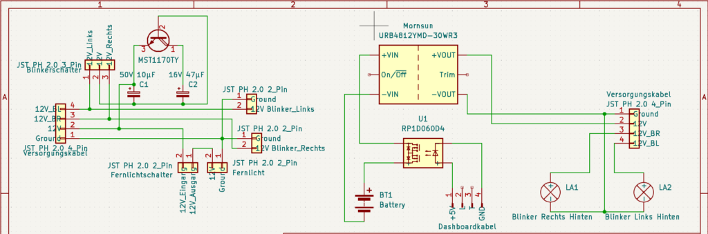
- An IC doing the blinky, like MST (Milestones) 1170TY (LCSC Electronics link) See also: (Datasheet)
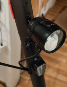
The Chip also calls for 10µF 63V and 47µF 10V capacitors, next higher value ones may also work, since these values are typical SMD capacitor values you might have trouble finding them as through-hole components (THT) (Hint: HIFI repair shops may sell them) - Headlights, your country might require you to pick something with an E-Number, K-Number, Z-symbol or other certifications, I used Busch + Müller IQ-X E 150 Lux Light and got a fitting mount for it, you can also 3D print one. I recommend screwing or clamping it to the frame since it weights a bit and might wobble around.
- The 12V turn lights for front and rear, Motorcycle shops have them, or you can use those made for other scooters like ePowerFun 2, VMAX VX2/4, Sparrow 2 (Respective links to parts shops) (here is a link to a picture of how it could look like: ImgBB Link
- Matching Grips in Color and Form, e.g. if you have black blinkers you might opt for black grips (Link)
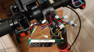
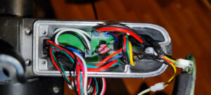
Images of the finished assembly
Lessons learned:
- Crimping connectors this small is an excercise in patience and left me completely frustrated and drained, in the end I opted for pre-crimped connector sets
- Being impatient about drilling into a metal bar with an internal Y-Structure will break your drill bits, work it really slowly… Use cutting oil and quality drill bits, clamp it and if available use a bench drill…
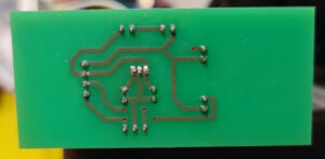
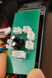
- IC Chips are sensitive to heat, get a few more than intended if this is your first time making and soldering your own PCB, the chip I used also has a temperature cut-off, my circuit only worked after letting it cool down for a while
- Check the specs yourself if you are working with LED lights, I burnt thru 2 of them since they claimed to also run up to 56V but most are actually only made for 12V or have no internal resistor at all
- If in doubt, ask your nearest Hackspace if you can use proper tools and if someone is willing to show you how to use them correctly
- Gluing the turnlights onto the handlebar seemed like an easy and obvious choice at first, but when they broke getting the glue off was annoying. Screw it!
Hi there! This post couldn’t be written much better!
Reading through this article reminds me of my previous
roommate! He constantly kept preaching about this.
I most certainly will send this article to him. Pretty sure he’s going to
have a very good read. Thanks for sharing!
You’re so interesting! I do not believe I’ve truly read through a single thing like that before.
So great to find someone with original thoughts on this topic.
Seriously.. thanks for starting this up. This website is one thing that’s needed on the internet, someone with
some originality!